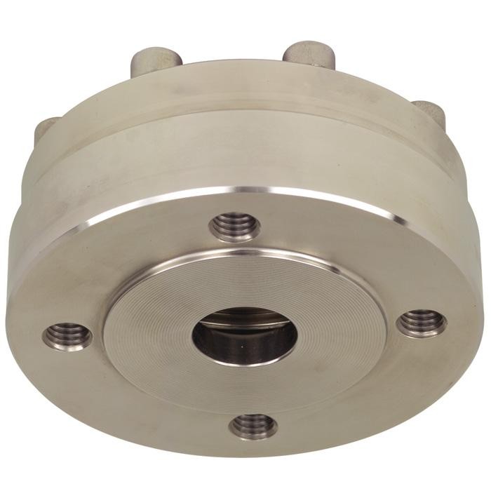
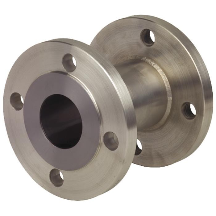
Description
Process connection
For flanges following EN 1092-1 / ASME B 16.5
Nominal sizes see drawing and tables
Sealing faces, Form B1 or ASME RF 125 … 250 AA
Pressure rating
PN 6 … 400 or class 150 … 2500
Pressure ranges
Preferably assembled on pressure gauges
NS 63, 100, 160 or pressure transmitters, measuring ranges 0 … 0.6 to 0 … 400 bar
Body and material of wetted parts
Stainless steel (AISI 316L) Measuring instrument connection
Pressure gauge or transmitter directly welded, process pressure transmitter with threaded adapter
System fill fluid
KN2, Silicone oil
Options
Process connection
- Sealing faces per EN 1092-1, Form B2 or per ASME B 16.5, RF 125 AA, 500AA, RFSF; EN 1092-1 groove and tongue; projection and recess; ASME B 16.5 snap ring groove Form RJF (limited for special materials, please inquired
- Flame arrester approved for Zone 0
Measuring instrument connection
- Capillary, when ordering please specify: length of capillary
- Cooling tower (for process temperature >140 °C)
Material of wetted parts
- Stainless steel 1.4435, 1.4541, 1.4571, 1.4462,
- Monel 400, Hastelloy C276, Inconel 600, Incoloy 825, tantalum, Hastelloy B2, C4, C22 and nickel
Capillary
- Custom lengths between 1 and 15 m
- Soft polyethylene or PTFE armour