Description
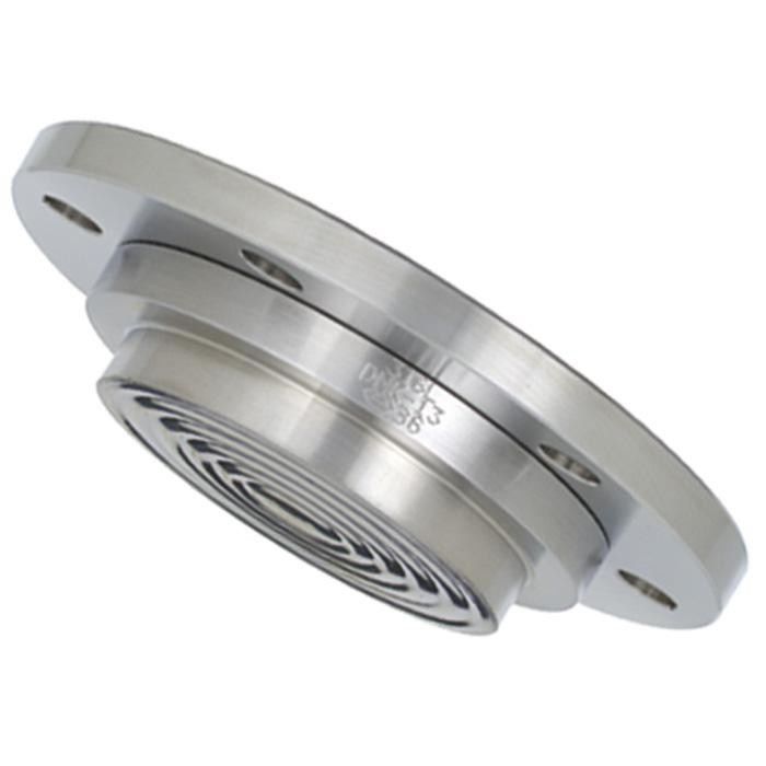
Process connection
Sealing face, Form B1 or ASME RF 125 … 250 AA For flanges following ASME B 16.5, 1″, 2″, 3″, 4″
Nominal size: see drawing and tables on datasheet
Pressure rating
Class 150/300
Pressure ranges
preferably mounted to pressure gauges NS 63, 100, 160 or pressure transmitters, Pressure ranges 0 … 15 to 0 … 600 psi
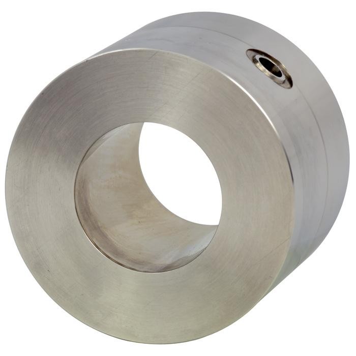
Housing and material of wetted parts
Stainless steel (AISI 316L)
Measuring instrument connection
Pressure gauge or transmitter directly welded, process pressure transmitter with threaded adapter
Options
Process connection
- Larger nominal sizes
- Other flange connections on request
- Sealing faces per EN 1092-1, form B2 or per ASME B 16.5, RF 125 AA, 500 AA, RFSF; EN 1092-1 groove and tongue; projection and recess; ASME B 16.5 snap ring groove form RJF (limited for special materials, please request)
- Flame arrester approved for zone 0
Material of wetted parts
- Staniless steel 316TI, 316, 321, Monel, Hastelloy B3, C22, C276, tantalum
- PFA coating max. +500 °F
- ECTFE (Halar®) coating max. +300 °F
Measuring instrument connection
- Capillary, when ordering please specify: length of capillary
- Cooling tower (for directly mounted gauge when fluid temperature > +284 °F)
Capillary
- Custom lengths between 3 and 25 ft.
- White PVC – Armor protection