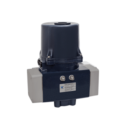
VTMR Series Spring Return Electric Actuator
The VTMR series spring return electric actuator is designed for mechanical fail-safe positioning of valves or dampers upon loss of supply power. The VTMR is for used in environments where reliable automatic closing or opening is required upon loss of power. When powered, the VTMR operates like a normal quarter-turn electric on-off or modulating actuator. Under normal powered conditions, the actuator and spring are held stationary through an electromechanical brake system. When power is lost, the spring is activated and returns the actuator to a predetermined fail-safe position.
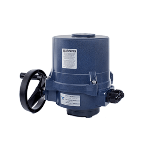
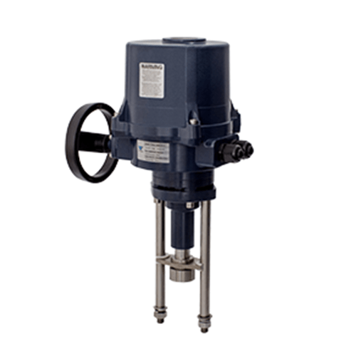
The optional manual override ensures that operators can manually rotate the valve or damper to a precise position and maintain a set position. Manual release is not required during the electric control operation.
Structure:
- Product Construction: Compact design to reduce space requirements
- Low Maintenance: Rugged design with mechanical springs reduces maintenance
- SIL Certification: Spring return electric actuator with SIL2
- Adaptive Mounting: Actuator flange and drive sleeves comply with ISO5211 standards. Versatile design provides flexible mounting options
- Position Indication: Position signal available in several outputs including 4-20ma and 0-10V
- Reliable: The VTMR provides a fail-safe mechanical solution for critical applications requiring the most reliable method assuring fail-condition in case of power loss